
Volume 2, Number 2, Spring 2002
The Fluidic Muscle: A 'New' Development
Stan Lightner, EdD
Department of Industrial Technology
University of Nebraska at Kearney
Rodney Lincoln, MEd
Raspet Flight Laboratory
Mississippi State University
ABSTRACT
The fluidic muscle is a pneumatic actuator with an extensive history of applications in the biomechanical field since the late 1950’s. However, its potential has not been extensively explored in robotics, motion control, material handling, and other industrial applications. This research compared the force output of a fluidic muscle with a pneumatic cylinder. The results demonstrated a higher generation of force by the fluidic muscle in contrast to the pneumatic cylinder at pressures from three and one-half to six bars. It is recommended further research be conducted to help determine appropriate industrial applications for the fluidic muscle.
INTRODUCTION
Development of the fluidic muscle began in artificial limb research of the 1950s and 1960s1, 2. Of particular note is the research conduced by J.L. McKibben, who developed an orthotic appliance for polio patients utilizing the device3. Thus source for one of the names given for this apparatus, the McKibben pneumatic artificial muscle. It is also known as the McKibben actuator, an air muscle, a braided pneumatic muscle actuator, and as a pneumatic muscle actuator (PAM)4, 5, 6, 7. It was commercialized by the Bridgestone Rubber Company of Japan in the 1980’s8 and more recently by the Shadow Robot Company5 (2001) and by FESTO9 Corporation (2001). At about the same time as the work by Bridgestone, the pneumatic muscle was redesigned by Dr. Jack Winters for the development of biomechanical realistic skeletal models10.
HISTORY
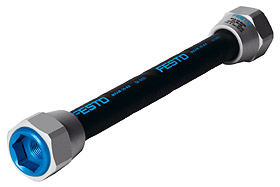
Richard H. Gaylord invented the fluidic muscle in 1955, with assignment of the 1958 patent granted to the Clevite Corporation of Cleveland, Ohio. Gaylord described the actuator as “an elongated expansible tubular means surrounded by a woven sheath forming an expansible chamber which contracts in length when expanded circumferentially.”11 In practice, the actuators are constructed by wrapping a synthetic or natural rubber tube with a man made fiber, such as Kevlar, at a predetermined angle. The fiber wrapping is then given a protective rubber coating and metal fittings are attached at each end (see fig. 1). When a fluid under pressure is applied to the interior of the muscle, it contracts in length, expanding radially resulting in linear motion.
|
Fig 1 |
|
Traditionally, three different types of actuators, pneumatics, hydraulics, and electrical, are used in applications such as robotics, motion control, or material handling.
They each have their advantages and disadvantages and should be evaluated as to the appropriateness for a given situation. A brief comparison of their characteristics is located in Table 1.
|
Table 1. Comparison of traditional actuators
|
||
|
Actuator |
Advantages |
Disadvantages |
|
Electrical |
Very accurate positioning and velocity control possible. Silent, and relatively inexpensive. |
Sparking limits use in hazardous environments. Low power and torque to weight ratios. |
|
Hydraulic |
Brute strength, essentially zero compressibility, excellent power to weight ratio. |
Leaks, lower reliability, higher maintenance, expensive, loud, flammable fluids, heat generating. |
|
Pneumatic |
Inexpensive, rapid response, simple and easy to control. |
Loud, compressible fluid, difficult to control position. |
Given the problems associated with the compressibility of the fluid and position control12, 4, there has been limited use of pneumatic cylinders in advanced robotics13. Consequently, some research has been directed toward other forms of actuator technology, which use active materials. This includes piezo-electric actuators based on materials such as PMN (lead magnesium niobate), quartz, and PZT (lead zirconate titanate). These actuators have positive inherent characteristics including their compactness, high position accuracy, very rapid response speeds, and the high generation of force per unit volume. However, the primary application of this technology is focused in micro-actuators and micro-manipulation14, 4. Another line of research has focused on the Shape Memory Effect (SME), based on the dimensional changes of nickel-titanium and other alloys as the temperature varies. However, most applications of the SME have been limited due to drawbacks, including the degradation of the SME over time, inefficient power utilization, control problems, and extended cycle times15, 4.
A third line of research is directed at electro-rheological and magneto-rheological fluids. These are fluids in which dramatic increases in viscosity are achieved by the application of electrical or magnetic stimuli to the respective fluid. The degree and speed of the change in viscosity can be controlled by the manipulation of the stimuli, resulting in a fluid that can change from a free flowing liquid to a semi-solid virtually instantaneously, or gradually over a predetermined amount of time. The return from a semi-solid to that of a low viscosity liquid is equally manageable by regulation of the stimuli. There has been research into the application of these fluids in the industrial and medical fields, resulting in some interesting prototypes, instrumentation, and experimental equipment, but it is limited due to the relative immaturity of the technology16, 17, 18, 19, 20.
EXPERIMENTAL DESIGN
Given the restrictions of the more traditional forms of actuators and the relative immaturity of some of the more promising alternatives, a viable alternative may be the fluidic muscle. Therefore, an experiment was designed with the purpose of comparing a fluidic muscle to a pneumatic cylinder. It is acknowledged the design of the experiment does not take into account the different surface areas within the actuators. The experiment was designed to compare the force output of actuators, which occupy roughly the same volume of space, a factor in many design decisions.
A test fixture (see Figs. 2 & 3) was designed and fabricated which could hold either a 10mm X 200mm fluidic muscle manufactured by FESTO®, or a 15.9mm (.625”) X 38.1mm (1.5”) Airpel® pneumatic cylinder manufactured by Airpot®. The sizes were selected as they occupy approximately the same volume of space. The brands were chosen as they represent high quality components from well-known and respected companies in the fluid power industry. The base of the fixture was made from 4” X 15” X ½” SAE 1018 steel plate in order to minimize the possibility of flexing from the force generated by the actuators. Custom steel mounting brackets were manufactured to hold the actuators and a load cell on the base. Care was taken to insure accurate alignment of the actuators and the load cell in order to avoid any interference, or external forces, especially those that would cause side loading of the pneumatic cylinder.
Test Fixture with Pneumatic Cylinder
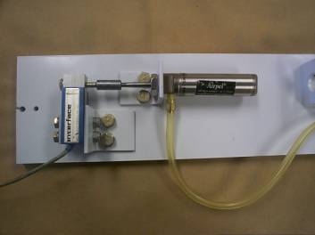
Figure 2
Test Fixture with Fluid Muscle
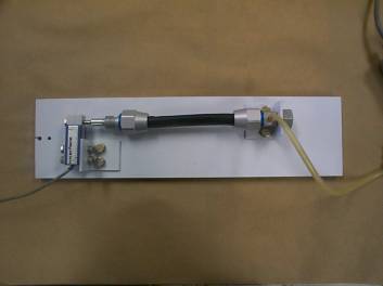
Figure 3
A Sealed Superbeam Load Cell model SSB-AJ-100 from Interface Inc. was selected as the load cell for the test fixture. This choice was made due to its capability to measure a force up to 445 Newtons. The manufacturer recommends an excitation voltage of 10 VDC for this model with the output signal being generated by a 350 Ohm internal bridge. Prior to installation on the test fixture, the load cell was calibrated using a Low Drift Burr-Brown Instrumentation Amplifier, model 3660J and supporting circuit. The gain on the amplifier has a range of 1 to 1000. Therefore, a setting of 300 was selected in order to avoid exceeding the rated output of the amplified of ± 10 volts. An existing Leader triple output bench top linear power supply was utilized to provide the necessary excitation voltages to the amplifier and load cell of ± 15 VDC and + 10 VDC respectively. The calibration test revealed a force of 1 Newton would create an output of .01915 volts from the load cell. A Fluke Model 83 III multimeter was used to measure the output signal during the calibration and the experiment.
The air pressure applied to the actuators was regulated with an adjustable regulator. To measure the air pressure, an Omega PX303-200G5V pressure transducer was plumbed into the pneumatic circuit and calibrated with the output voltage measured with a Fluke Model 83 III multimeter. This unit is rated at 13.8 bar, has an excitation range of 12 to 32 VDC, and has a linear output voltage from .5 to 5.5 VDC. Consequently, an output of .3623 volts is equal to 1 Bar of air pressure. Fifteen VDC was used as the excitation voltage since it was readily available from the power supply.
RESULTS
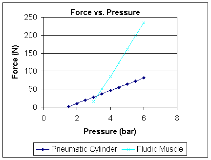
As seen in the following data chart (table 2) the output of the pneumatic cylinder ranged from a low of 1.775 Newtons at 1.5 Bars of pressure to a high of 81.651 Newtons at 6 Bars of pressure. In contrast, the output of the fluidic muscle ranged from 14.305 Newtons at 3 Bars of pressure to a high of 234.93 Newtons at 6 Bars of pressure. Initially, the pneumatic cylinder outperformed the fluidic muscle, responding at a lower air pressure and generating a higher output. However, as the air pressure increased, the fluidic muscle soon surpassed the pneumatic cylinder in force generated (table 3).
Table 2
| Bar |
|
Force (N) |
Force (N) |
|
|
|
Pneumatic Cylinder |
Fluidic Muscle |
| 0.0 |
|
|
|
| 1.5 |
1.775 |
|
|
| 2.0 |
9.58 |
|
|
| 2.5 |
18.586 |
|
|
| 3.0 |
27.591 |
14.305 |
|
| 3.5 |
36.597 |
49.857 |
|
| 4.0 |
45.524 |
86.088 |
|
| 4.5 |
54.608 |
123.834 |
|
| 5.0 |
63.588 |
160.222 |
|
| 5.5 |
72.671 |
198.907 |
|
| 6.0 |
81.651 |
234.93 |
Table 3
CONCLUSIONS
According to the manufacturers of fluidic muscles, they offer several advantages over traditional pneumatic actuators including less weight, lower energy consumption with equal or greater force output, no stiction, lower cost, higher power to weight ratio, and impermeability to dirt, sand, and dust9, 21, 5. Given the superior output, it appears fluidic muscles could replace pneumatic cylinders in some applications. The higher output also indicates fluidic muscles could be substituted for small hydraulic cylinders in certain situations.
As each product design generates its individual engineering challenges, it would be nonsensical to claim the fluidic muscle is an across the board substitution for a pneumatic cylinder. However, this actuator offers some unique characteristics that need to be explored by engineers, engineering technologists, and industrial technologists in a wide variety of fields including motion control, robotics, material handling, production equipment, and other areas. Application engineers and technologists in academia and in industry should be encouraged to consider the fluidic muscle when looking for an appropriate fluid motion actuator. Further research involving this actuator is encouraged, including that which would investigate the possibility of fluidic muscles powered by hydraulics.
References
1. Schulte, H.F. Jr (1961). The characteristics of the McKibben artificial muscle. In: The application of external power in prosthetic and orthotics. Washington, DC: National Academy of Sciences-National Research Council.
2. Gavrilovic, M.M. & Maric M.R. (1969). Positional servo-mechanism activated by artificial muscles. Medical and Biological Engineering, 7, 77-82.
3. Nickel, V.L., Perry, & Garrett, A.L. (1963). Development of useful function in the severely paralyzed hand. Journal of Bone and Joint Surgery, 45A(5), 933-952.
4. Caldwell, D.G., Razak, A., & Goodwin, M. (1993) Braided pneumatic muscle actuators. Proceedings of the IFAC workshop on intelligent autonomous vehicles (pp. 507-512). Southampton, United Kingdom.
5. Shadow Robot Company (2001, November 18). Welcome to Shadow. Retrieved October 9, 2001 from http://www.shadow.org.uk/
6. Chou, C.P. & Hannaford, B. (1996). Measurement and modeling of McKibben pneumatic artificial muscles [Electronic Version]. IEEE Transactions on Robotics and Automation, 12, 90-102.
7. Lilly, J. H. (n.d.). Adaptive tracking for pneumatic muscle actuators in bicep and tricep configurations. Retrieved January 21, 2002 from University of Louisville, Department of Electrical and Computer Engineering Web site: http://pyramid.spd.louisville.edu/~jhlill01/pm.pdf
8. Inoue, K. (1988). Rubbertuators and applications for robots. In Bolles, R. & Roth, B. (Eds.), Robotics Research: The 4th International Symposium (pp. 57-63). MIT Press, Cambridge, MA.
9. FESTO, AG & Co. (2001). Fluidic Muscle MAS. Retrieved July 5, 2001 from http://www.festo.com/hm2001/eng/1001.htm
10. Hannaford, B. & Winters, J.M. (1990). Actuator properties and movement control: Biological and technological models. In J.M. Winters & S.L. Woo (Eds.), Multiple muscle systems: Biomechanics and movement organization (pp. 101-120). New York, NY: Springer-Verlag.
11. Gaylord, R.H. (1958). U.S. Patent No. 2,844,126. Washington, DC: U.S. Patent and Trademark Office.
12. Vockroth, R.W. (1994). Industrial hydraulics. Albany, NY: Delmar.
13. Calwell, D.G., Medrano-Cerda, G.A., & Goodwin, M. (1995). Control of pneumatic muscle actuators. IEEE Control Systems, 15, 40-48.
14. Intellimat (2000). Welcome to the world of smart materials. Retrieved January 29, 2002 from http://www.smartmaterials.info
15. DYNALLOY, Inc. (n.d.). Flexinol. Retrieved January 31, 2002 from http://www.dynalloy.com
16. MEMICA (2000, April 24). Remote mechanical mirroring using controlled stiffness and actuators (MEMICA) homepage. Retrieved January 31, 2002 from http://ndeaa.jpl.nasa.gov/nasa-nde/memica/memica.htm
17. Nippon Shokubai Co., LTD. (n.d.). ER Fluid (Electro-Rheological Fluid). Retrieved January 29, 2002 from http://www.shokubai.co.jp/english/main/kaihatsu/txer/txer.htm
18. Jolly, M.R., Bender, J.W., & Carlson, J. D. (1998). Properties and applications of commercial magnetorheological fluids, SPIE 5th annual int symposium on smart structures and materials. San Diego: CA.
19. Lord Corporation Materials Division (n.d.). Commercial leader in MR technology. Retrieved January 29, 2002 from http://www.frictiondamper.com/default.htm
20. Carlson, J.D., Catanzarite, D.N., & St Clair, K.A. (1996). Commercial magneto-rheological fluid devices, In W. Bullough (Ed.), Proceedings 5th Int. Conf. on ER Fluids, MR suspensions and associated technology (pp. 20-28), World Scientific: Singapore.
21. Severn, J. (April, 2000). Pneumatic actuators with a difference. Industrial Technology. Retrieved October 2, 2001 from http://www.industrialtechnology.co.uk/2000/apr/west.html